
Very easy! Wireless Microcomputer TWE-Lite DIP
Very easy! Wireless Microcomputer TWE-Lite DIP (Twilight DIP)
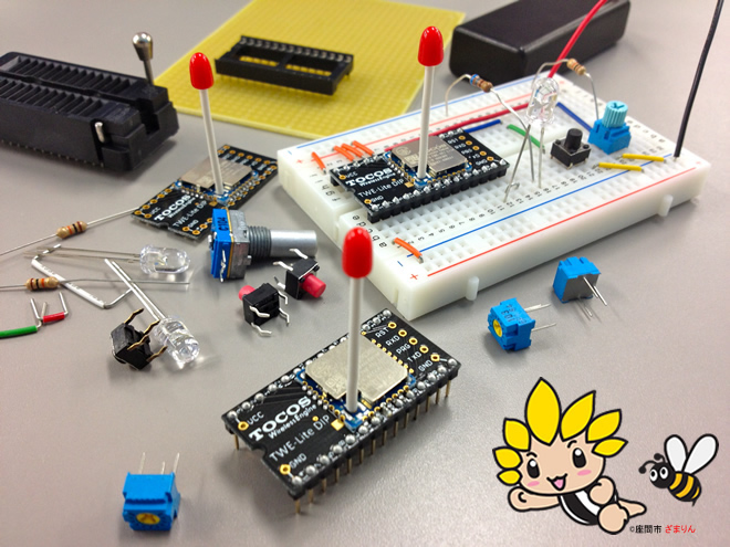
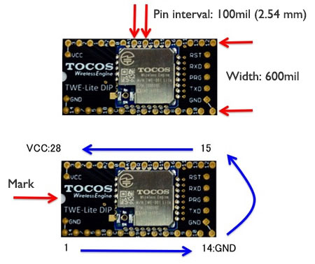
Very easy! Wireless Microcomputer TWE-Lite DIP (Twilight DIP) has been developed based on the concept of "easy and ready-to-use wireless module", by making the TWE-Lite into the shape of DIP-type IC with 2.54mm-pitch and 28 pins (600mil) and integrating the dedicated software.
The TWE-Lite DIP (Twilight DIP) is a wireless microcomputer that has a built-in 32-bit microcomputer and can conduct digital, analog and serial wireless communications, without any external control microcomputer. As the ready-to-use TWE-ZERO application software that does not require any program development is pre-installed, you can easily and immediately use the TWE-Lite DIP without any troublesome work.
Also, the TWE-Lite DIP (Twilight DIP) can be used as a general-purpose 32-bit microcomputer to freely create and use programs. Of course, the wireless functions are available. You can use Software Development Environment (SDK) that you can easily install and establish the development environment for software development, for free of charge. We also offer source codes of the standard built-in software.
Very easy! Part 1
As the shape is equal to that of standard 2.54 mm-pitch DIP-type IC, you will be familiar with it easily and you will use it without any questions even for the first time. As the TWE-Lite DIP can be directly mounted on a standard IC socket, universal board, and breadboard without a pitch converting board, working is easy.
Very easy! Part 2
Any complex operation such as software installation and initial value setting with PC connection prior to the use is not necessary and you can use the TWE-Lite DIP immediately after the wiring of peripheral electronic circuit. As external control microcomputers and PIC are not necessary and the TWE-Lite DIP can independently operate, setting is easy.
Very easy! Part 3
The wireless connection system supports the point-to-point communications in accordance with the standard specification, IEEE802.15.4, as well as the one-hop relay function. With a simple network configuration, operation is easy.
*ZigBee protocol stack is not used.
To Purchase
please contact us to purchase.
Notes for obtaining longer signal range
As an antenna is the important part to send/receive radio waves for wireless communications, please understand the following descriptions and keep it in a better condition.
- Stretch the antenna straight and use it by standing vertically.
- You can obtain the longest signal range when there is no obstacle between antennae and the antenna position is high enough (*1).
- If there is a metal object around the antenna, the performance will decline.
- Sensitivity is high around the antenna axis and it is very little right above and right below.
*For the communications with the distance of 1 km between terminals, height of approximately 3 meters is necessary.
Measurement of signal range
Operating voltage
The input voltage is 2.3 V ~ 3.6 V. Please use the voltage within the rated voltage. Please be careful of the direction of VCC (plus side of the power supply) and GND (minus side of the power supply).
Instructions for Use
- As the antenna has been certified as the set, antennae other than matchstick antenna should not be used.
- Do not change the length of matchstick antenna.
- f you repeatedly fold and stretch the antenna by applying stress to the matchstick antenna root, it may cause a fracture.
- Applying of voltage of 3.6V or higher to the power supply input may cause failure.
- If the VCC (plus side of the power supply) and GND (minus side of the power supply) connection direction is opposite, it may cause failure.
Let’s operate! (How to use: For Beginner Level)
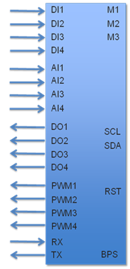
I/O Signal
TWE-Lite DIP (Twilight DIP) has various I/O terminals as shown below.
| Signal name | Function | Descriptions |
|---|---|---|
| DI1, DI2, DI3, DI4 | Digital input | |
| AI1, AI2, AI3, AI4 | Analog input | |
| DO1, DO2, DO3, DO4 | Digital output | |
| PWM1, PWM2, PWM3, PWM4 | PWM output | |
| TX, RX | UART serial | UART |
| SCL, SDA | I2C serial | I2C |
| RST | Reset input | |
| M1, M2, M3 | Mode selection | For setting |
| BPS | UART speed selection | For setting |
Upon the power activation, all the outputs are set to High. Inputs are set to Low (GND) when turned on.
Basic Operation
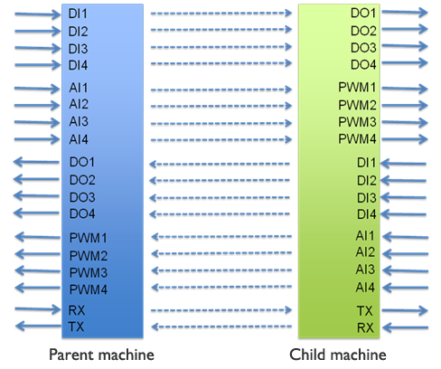
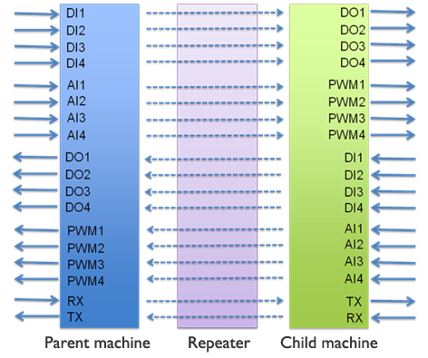
As shown in the diagram, wireless communications of the signals are carried out in two ways between the parent machine and child machine. Please understand the signal flow first, because this is the basic. 4 types of digital signals, 4 types of analog signals, and 1 type of serial signal can be transmitted in the wireless communications.
In the default condition, communications between only 1 pair / 1 group is available to secure simple operation; however, you can perform communications between multiple pairs and groups by changing the settings. Please see Setting of Frequency Channel and Setting of Application ID.
Wireless communications for digital signals (DI -> DO)
Two-way digital signal communications are available between the parent machine and the child machine. For example, a signal input to Digital Input 1 (DI1) of the parent machine will be output to Digital Output 1 (DO1) of the child machine. A signal input to the Digital Input 1 (DI1) of the child machine will be output to Digital Output 1 (DO1) of the parent machine. In the same way, DI2 and DI3 deliver transmit to DI4 and DO4.
Wireless communications for analog signals (AI -> PWM)
Two-way analog signal communications are available between the parent machine and the child machine. For example, a signal input to Analog Input 1 (AI1) of the parent machine will be output to PWM Output 1 (PWM1) of the child machine. A signal input to the Analog Input 1 (AI1) of the child machine will be output to PWM Output 1 (PWM1) of the parent machine. In the same way, A2 transmits signals to PWM2, A3 to PWM3, and A4 to PWM4. PWM is the method for changing the voltage by changing the digital pulse width. If the pulse width is widened, the voltage will become higher. If it is narrowed, the voltage will become lower.
Although the initial frequency value for PWM is 1 kHz, you can change it on Setting Change (Interactive) Mode.
Wireless communications for serial signals (TX -> RX)
Two-way analog signal communications are available between the parent machine and the child machine. UART serial signals (TX, RX) are used for communications. For the method for connection and communications, please see For Advanced Level.
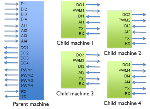
1-to-multiple communications
Contents of the 1-to-1 communications between the parent machine and the child machine can be transmitted to other terminals. In other words, signals of the parent machine can be received by multiple child machines at the same time. Therefore, by assigning the signals to be used for multiple terminals, the parent machine can make a behavior to communicate with individual child machines. For example, as shown in the diagram, 1 parent machine can communicate with 4 child machines. In this case, the basic operation is the same and all the child machines receive the same signals from the parent machine and they use only the necessary signals. Therefore, communications between the child machines are impossible and all the child machines receive the same contents of serial communications from the parent machine. In the same way, you can have multiple parent machines and you can divide signals. In any case, the basic operation is not changed.
Note: Please connect all the unused analog input (AI) terminals to VCC (plus side of the power supply) when sending analog signals. For example, as the child machine 1 only uses AI1 in the diagram below, AI2, AI3 and AI$ should be connected to VCC (plus side of the power supply).
Repeater
Repeater is a wireless terminal that is put between the parent machine and the child machine to extend the signal range. The repeater transmits signals from the parent machine to the child machine as they are and it also transmits signals from the child machine to the parent machine as they are. You can put multiple repeaters for operation; however, repeating is 1 hop. Please be careful that installing of many repeaters will cause overproduction of copy packets. If a repeater receives packets from another repeater, the packets will be deleted without being sent.
*TWE-Lite DIP) Twilight DIP) standard application limits the repeating to 1 hop so that the network can maintain simple structure. ToCoNet supports multiple hops and tree network.
Pin Layout
Outline of the TWE-Lite DIP (Twilight DIP) is 28-pin (600 mil) DIP shape. The terminal number is assigned in the same way as an ordinary DIP-type IC. When viewed from the top by placing the semicircular notch mark to the left, the lower left one is Pin No.1 and terminals should be counted counterclockwise. The lower right one is Pin No.14, the upper right one is Pin No.15 and the upper left one is Pin No.28.
| Function | Signal name | Serigraph | Pin | Pin | Serigraph | Signal name | Function | |
|---|---|---|---|---|---|---|---|---|
| Power Supply Ground |
GND | GND | 1 | 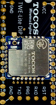 |
28 | VCC | VCC | Power Supply (2.3 ~ 3.6V) |
| I2C Clock | SCL | 14 | 2 | 27 | 3 | M3 | Mode Setting Bit 3 | |
| UART Receiving | RX | 7 | 3 | 26 | 2 | M2 | Mode Setting Bit 2 | |
| PWM Output 1 | PWM1 | 5 | 4 | 25 | I | AI4 | Analog Input 4 | |
| Digital Output 1 | DO1 | 18 | 5 | 24 | A2 | AI3 | Analog Input 3 | |
| PWM Output 2 | PWM2 | C | 6 | 23 | 0 | AI2 | Analog Input 2 | |
| PWM Output 3 | PWM3 | I | 7 | 22 | A1 | AI1 | Analog Input 1 | |
| Digital Output 2 | DO2 | 19 | 8 | 21 | R | RST | Reset Input | |
| Digital Output 3 | DO3 | 4 | 9 | 20 | 17 | BPS | UART Speed Setting | |
| UART sending | TX | 6 | 10 | 19 | 15 | SDA | I2C Data | |
| PWM Output 4 | PWM4 | 8 | 11 | 18 | 16 | DI4 | Digital Output 4 | |
| Digital Output 4 | DO4 | 9 | 12 | 17 | 11 | DI3 | Digital Input 3 | |
| Mode Setting Bit 1 | M1 | 10 | 13 | 16 | 13 | DI2 | Digital Input 2 | |
| Power Supply Ground | GND | GND | 14 | 15 | 12 | DI1 | Digital Input 1 |
Setting of Parent Machine, Child Machine and Repeater (M1, M2, M3)
Basic operation of the TWE-Lite DIP (Twilight DIP) is the wireless communications between the parent machine and the child machine. Therefore, the terminals should be set to either one. This setting is made with the combination of M1, M2 and M3 (Mode Setting Bit). To select "G", connect the signals to GND (minus side of the power supply). To select "O", no wiring is needed.
You can extend the signal range by putting a repeater between the parent machine and the child machine. In this case, select Repeater when setting up. Repeating is for 1 hop. Connect M2 to GND (minus side of the power supply). Default value without setting is "Child machine: Continuous Mode".
| M3 | M2 | M1 | Mode name | Functions |
|---|---|---|---|---|
| O | O | O | Child machine: continuous | Constant receiving status. Send upon a change in the input. Response: quick. Battery life: shorter. |
| O | O | G | Parent machine: continuous | Constant receiving status. Send upon a change in the input. Response: quick. Battery life: shorter. |
| O | G | O | Repeater: continuous | Constant receiving status. Response: quick. Battery life: shorter. |
| O | G | G | Child machine: continuous (0.03 seconds) | Constant receiving status. Send by repeating the input value every 0.03 seconds. Response: quick. Battery life: shorter. Communications from the parent machine to the child machine: slower. |
| G | O | O | Child machine: intermittent (1 second) | Power saving mode. Switching to the communication mode every 1 second. Battery life: longer than the continuous mode. Response: Max. 1 second. |
| G | O | G | Unused | |
| G | G | O | Unused | |
| G | G | G | Child machine: intermittent (10 seconds | Power saving mode. Switching to the communication mode every 10 seconds. Battery life: the longest. Response: Max. 10 seconds. |
During stopping on the power saving mode, the power supply of the wireless part is turned off and transmission is enabled. A built-in timer periodically turns on the wireless part.
Child machine: Connect all the unused Analog Input (AI) pins to VCC (plus side of the power supply) during the continuous mode.
Parent machine: Connect all the unused Analog Input (AI) pins to VCC (plus side of the power supply) during the continuous mode.
Baud rate setting for the UART serial communications (BPS)
TWE-Lite DIP (Twilight DIP) can conduct UART communications with external microcomputers. In this case, you can select the baud rate (communications speed). To select "G", connect the BPS signal to GND (minus side of the power supply). To select "O", no wiring is needed. The default value without setting is "115200 bps". To select 38400 bps, connect the BPS signal to GND (minus side of the power supply).
| BPS | Function |
| O | Serial communications: 115200 bps |
| G | Serial communications: 38400 bps |
* To set to the speed other than 38400 bps, please use Setting Change (Interactive) Mode.
How to use
- For beginner level (Let’s operate!)
- For intermediate level (Selecting of parent machine, child machine, and repeater)
- For advanced level (Connecting with PC, detailed settings, serial communications)
- For application level (Programming)
- For wizardly
Wireless Products
- Overview
- Wireless Products Overview
- Wireless Engine
- TWE Lite DIP
- TWE-Lite
- TWE-REGULAR
- TWE-STRONG
- Software
- ToCoNet
- TWE-ZERO
- Evaluation, Development
- Evaluation & Development Kit
- Sensor Network Evaluation Kit
- Antenna
- Avaliable Antennae
Technical Information
- RFID
- 920MHz_vs_24
- IEEE802.15.4
- Protocol Stack
- ZigBee
- Wireless Sensor Networks
- Energy Harvesting Technology
- M2M Wireless Communications
- HEMS / BEMS / FEMS / CEMS
- Internet of Things