
ZigBee/IEEE802.15.4 Measurement Tool
This section describes the ZigBee / IEEE802.15.4 Measurement Tool available for ZigBee / IEEE802.15.4 Evaluation and Development Kit.
Network Discovery Tool
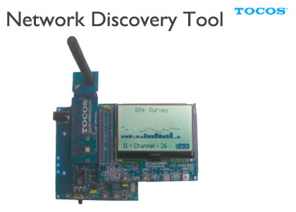
Equipped with the simplified spectrum analyzer function, this tool observes radio waves of 2.4GHz band.
Wireless communication is affected by noise. The use of this tool at the time of measuring signal range or confirming communication quality allows you to check radio waves of 2.4GHz band.
The tool operates with the sensor node (large, with the LCD screen), and obtain the information on the radio wave environment (Site Survey: simplified spectrum analyzer for each channel) and the existing 802.15.4/HenNet/ZigBee PRO network.
Download and Write
- Download (for TWE-EK-002)
- Write NetworkDiscoveryTool_JN5148.bin found in decompressed \Build into the sensor node (large, with the LCD screen).
Communication Quality Evaluation Tool (PER)
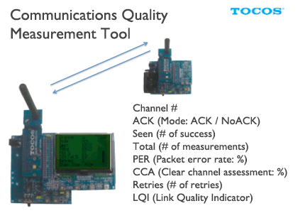
This is the tool to evaluate communication quality that measures PER (i.e. packet error rate).
The tool allows you to check the signal range, the impact of obstacles, and the communication quality of the location where the terminal is located.
Measurement requires a wireless sensor node (large, with the LCD screen) as well as a wireless sensor node (small, without the LCD screen).
Download and Write
- Download (for TWE-EK-002)
- Write AN1006_PER_Master_JN5148.bin found in decompressed JN-AN-1006-PER-Test\AN1006_Master\Build into the wireless sensor node (large, with the LCD screen).
- Similarly, write AN1006_PER_Slave_JN5148.bin found in JN-AN-1006-PER-Test\AN1006_PER_Slave\Build into the wireless sensor node (small, without the LCD screen).
Execution
- Power on the wireless sensor node (large, with the LCD screen) and the wireless sensor node (small. Without the LCD screen).
- The wireless sensor node (large, with the LCD screen) allows you to complete basic settings by means of menu manipulation on the screen.
*Set the Power Mode to High if you use TWE-001 STRONG.Options Channel: 11 <- Test channel (26 cannot be selected) Power Mode: Low <- Low for TWE-001, or High for TWE-001 STRONG Power Level: 24 <- Output attenuator (24=-0db, 16=-11.5db, 8=-23db, and 0=-34.5db) Retries: 3 <- Number of retries in the MAC layer LEDs: Enabled Done <- Test started Up Down Select Button1 Button2 Button3
- Select items using Buttons 1 and 2, and change values with Button 3. When setting is completed, move to "Done" and press Button 3.
- When communication with the wireless sensor node (small, without the LCD screen) is checked, the following screen appears:
Channel:            11          <- Test channel (26 cannot be selected)
Mode:                 Ack      <- Communication mode (Ack or No Ack)
Seen:                 5590   <- Number of successful communications
Total:                  5635    <- Number of communications
PER %:               0.8      <- Packet error rate
CCA Fail %        0.0      <- CCA fail rate
Retries               3           <- Retry setting
Chan                Stop          Mode
Button1       Button2       Button3
Start Measurement
- Place the wireless sensor node (small, without the LCD screen) at the measuring point.
- Set the wireless sensor node (large, with the LCD screen) well close to the wireless sensor node (small, without the LCD screen). (Set the channel mode and start PER measurement)
- Move the wireless sensor node (large, with the LCD screen) to the other measuring point such that radio waves are not disconnected wherever possible.
- Press Button 2 (STOP/START) to suspend measurement.
- Press Button 2 again to restart measurement (statistic information will be initialized).
*The longer the distance is, the longer it takes time to restart, which could lead to time-out. In this case, repeat suspension and restart several times.
*If nothing occurs, go back to the setup process. Involving several communications, the setup process might fail where the packet error rate is high. Therefore, it might be effective to move a little closer to the sensor node for setup and then go away from the node. - When the counter Seen counts up to a given number, press Button 2 to suspend measurement and record the measured value.
- Move to the next measuring point.
Other Information
- The difference between the Ack and NoAck modes is which of the two nodes to send packets first.
Ack: Communication to send packets from the wireless sensor node (large, with the LCD screen), receive the packets with the wireless sensor node (small, without the LCD screen), and then receive ACK.
NoAck: Communication to send packets from the wireless sensor node (small, without the LCD screen) without Ack, and see how many times the packets are received with the wireless sensor node (large, with the LCD screen).
*This measurement is also effective where operation is unstable. However, it cannot directly compare the values with those of the Ack mode. - If you want to measure a new PER, stop measurement (with Button 2) and then press Start (Button 2) again. This process resets the counter and communication restarts.
- Communication could not successfully start in the poor communication condition. Move to the location with a better communication condition to check that communication starts, and then move to the measuring location.
- The packet size at the data payload area is 4 bytes, and the total packets account for 23 bytes.
*Details: Header in the PHY layer of 6 bytes / header in the MAC layer of 11 bytes (source: short, destination: short) / data payload of 4 bytes / FCS of 2 bytes = total 23 bytes
Measurement Precautions
- The signal range is also affected by surrounding noise. If the distance cannot be longer where there are not many obstacles, check the condition of radio waves using the network discovery tool. Changing the communication channel to a location with low noise could improve communication quality.
Wireless Products
- Overview
- Wireless Products Overview
- Wireless Engine
- TWE Lite DIP
- TWE-Lite
- TWE-REGULAR
- TWE-STRONG
- Software
- ToCoNet
- TWE-ZERO
- Evaluation, Development
- Evaluation & Development Kit
- Sensor Network Evaluation Kit
- Antenna
- Avaliable Antennae
Technical Information
- RFID
- 920MHz_vs_24
- IEEE802.15.4
- Protocol Stack
- ZigBee
- Wireless Sensor Networks
- Energy Harvesting Technology
- M2M Wireless Communications
- HEMS / BEMS / FEMS / CEMS
- Internet of Things